Overview Drawing Area
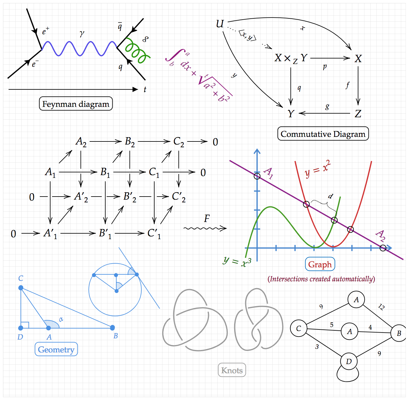
This feature is very powerful. It helps you not only draw Diagrams/Graphs, but also insert any formula at any position and rotation. In case the supported Latex Layout is not enough, you always have this option as a free-style layout.
Step 1: To insert a Drawing Area into Math Editor, click  . A Grid View will appear as shown below:

Step 2: When the Drawing Area appears, the menu bar will change into:

- Click (1) to turn on/off the grid view of the drawing area
- Drag (2) to the left/right to modify the square size of the grid
- Click (3) to snap formulas to the grid when moving them with the mouse
- Click (4) to turn on/off the grid only on editing
- Click (5) to save any math formula in Math Mode Notice: Zoom mode for objects in Drawing Area is not yet supported.
Tool bar
Section titled “Tool bar”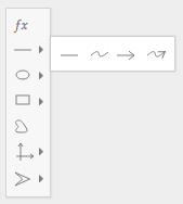
The Tool bar is a collection of action bars that provides many options for drawing on the Drawing Area. You can find its options shown below.
- Display Text in Drawing Area
Step 1: Click  on the tool bar to insert a Text Box into the Drawing Area (all text in the Drawing Area is in Math Mode; Text Mode is not supported yet). You will see something like this:
Step 2: Click on the Text Box object that has just appeared. The menu bar will change to:
on the tool bar to insert a Text Box into the Drawing Area (all text in the Drawing Area is in Math Mode; Text Mode is not supported yet). You will see something like this:
Step 2: Click on the Text Box object that has just appeared. The menu bar will change to:

- Click (1), (2), (3) to set/remove the Text Box’s border. Border styles include Rectangle, Ellipse, and Circle
- Click (4) to adjust border-width ( multiple border sizes included thin, medium, thick…)
- Click (5) to set border-color
- Click (6) to fill in the Text Box’s background-color
- Drag (7) to the left/right to rotate a Text Box
- Click (8) to change text-color
- Click (9) to change font-size
- Click (10) to remove the Text Box object from the Drawing Area
- Border

Step 1: Click (1) to turn border-style into a Rectangle:

Drag  to the left/right to round the edges of a Text Box’s border by adjusting the corner radius
Click
to the left/right to round the edges of a Text Box’s border by adjusting the corner radius
Click  to apply frame-stroke-style
Step 2: Click (2) to change border-style into an Ellipse
Step 3: Click (3) to change border-style into a Circle
- Connected Arrow

There are various options you can modify for Arrow:

- Click (1), (2), (3) to switch between Straight Line, or Curve Line, or Curve Line with 2 control points
- Click (4), (5) to change Arrow Tail/Head A common scenario is wanting a hole in the middle of an arrow. Click (6) to achieve that
- You will see 2 more options
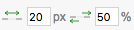 that allow you to change the position and size of the hole. Click and drag to increase/decrease the value, or double-click to change the value directly
 - Click (7) to change arrow thickness, and (8) to change arrow color
- Click (9) to remove the connected arrow object from the Drawing Area
- Commutative Diagram
The app supports features to quickly create a Commutative Diagram by following the steps below: Step 1: Insert a Text Box into the Drawing Area. You will see something like this:

Step 2: Insert another Text Box and move it to the right of the first one. Select the first Text Box. You will notice 3 arrows around the textbox. Click on any of them and drag to the position of the second textbox to create a connecting arrow. You can then double-click on a textbox to modify the text inside. Continue with the same steps to create something like the diagram below:

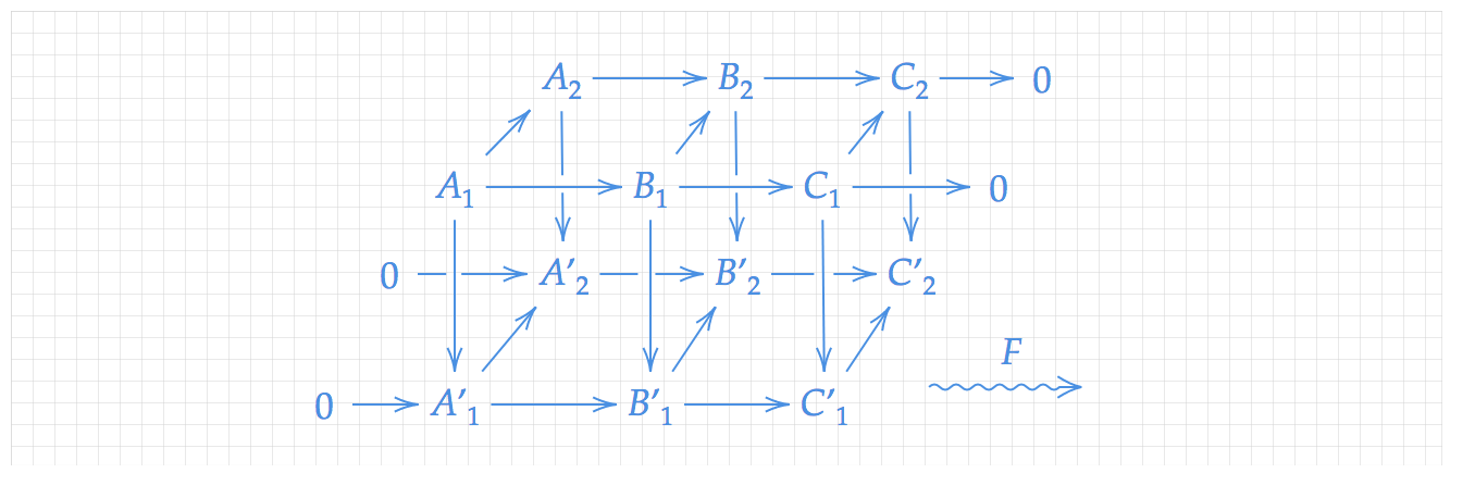
Step 3: By combining Connected Arrow options, you can create a Diagram like the one below:
You can find many types of lines on the toolbar: 
- Straight Line


There are many options you can use to modify it, as shown below:
- Click (1) and (2) to select styles of head/tail of a line
- Click (3) adjust line-width
- Click (4) to set line-color
- Click (5), (6) to add/remove a point (after adding one more point, the line will turn into a three-point shape)
- Click (7) to show collisions between two or more shapes
- Click (8) to hide collision points
- Click (9) to arrange the front/back order of a line object (relative to other objects)
- Click (10) to remove a line from the Drawing Area
- Curved Line


- Click on the curved line to see two points. Each point is connected to an attached point on the tangent of the curve. The attached point can be adjusted to create smooth curves.
- Click
 to bend the curve in reverse
 - Refer to the Straight Line options for other options
Straight Arrow

Straight arrow inherits the basic options of an arrow with a modified head.
Curved Arrow

Curved arrow inherits the basic options of a curved arrow with a modified head.
You can find many types of shapes on the toolbar:

and

- Circle
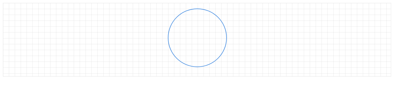
When you click on the circle, four points at each corner will appear, allowing you to modify the size of the circle. Options for a Circle Shape are shown below:

- Click (1) to adjust border-width ( multiple border sizes included thin, medium, thick…)
- Click (2) to set the circle’s border-color
- Click (3) to fill in the circle’s background-color
- Click (4) to apply frame-stroke-style
- Drag (5) to the left/right to rotate a circle
- Click (6) to show collisions between two or more shapes
- Click (7) to hide collision points
- Click (8) to arrange the front/back order of a line object (relative to other objects)
- Click (9) to remove a line from the Drawing Area
- Ellipse

Options for an Ellipse Shape are mostly the same as for a Circle Shape, except that when modifying the size, both width and height can be adjusted independently, whereas for a circle only the radius can be modified
- Segment of Ellipse (Arc)

Arc is used to display an angle in geometry. Compared to a circle, when you click on the segment, two yellow points will appear that allow you to adjust the length of the segment. Options for a segment are shown below:

- Click
 to show/hide two radii that start from the center of the ellipse and end at the two endpoints of the arc
 - Refer to the Circle options for other options Step 1: Insert a line into the Drawing Area, click on [icon] to add one more point to the line, and adjust the shape into an angle Step 2: Insert a segment and rotate it until it fits the angle

Step 3: By combining circle shapes, lines, and segments, you can create a complex shape like the one below:
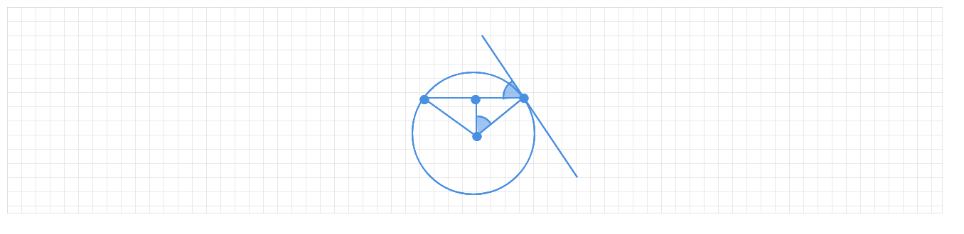
- Rectangle

There are many options for rectangle:

- Drag
 to the left/right to round the edges of a rectangle’s border by adjusting the corner radius
 - Other options can be found in the Circle options
- These are shapes that are related to rectangle
- Square

- Refer to the Rectangle options for Square options.
- Polygon
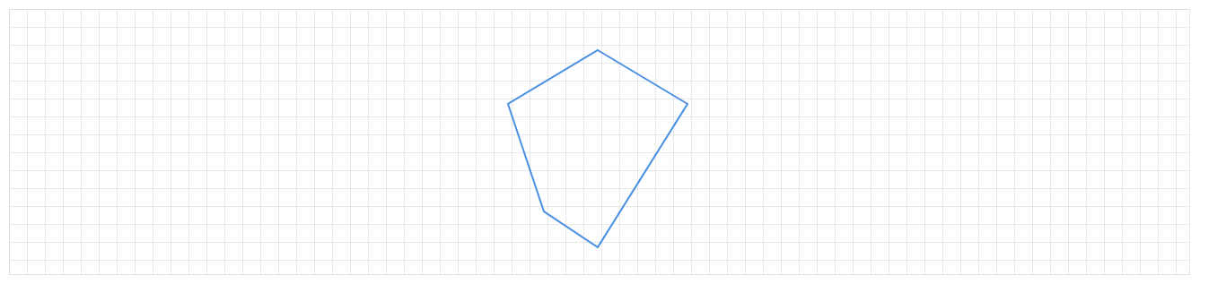
- Options for polygon are shown below:

- Click
 to add/remove a point (after adding one more point, the polygon will gain one more side)
 - Other options can be found in the Circle options
- Regular polygon
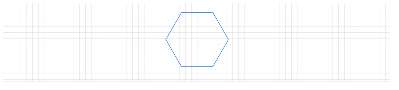
Options for Regular polygon:

- Click
 to add/remove a side of a regular polygon
 - Other options can be found in the Circle options
- Polycurve
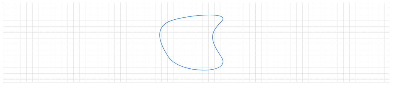
- Click
 on the tool bar to insert a Polycurve. Options for Polycurve:

- Click
 to bend the curve in reverse
 - Other options can be found in the Circle options
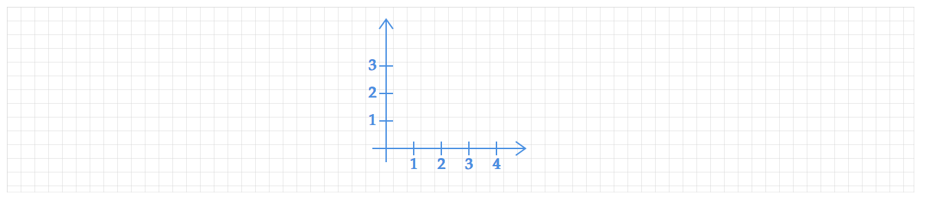
Axis and other types of coordinates are shown on the tool bar. Click  to see more options. Options for the Cartesian coordinate system are shown below:

Click  to enable the separator. When it is turned on, you can see some additional dependent options:

- Drag
 to the left/right to increase/decrease the separator distance
 - Click
 to adjust number-color
Other options can be found in the Circle options
to adjust number-color
Other options can be found in the Circle options
- Wave

Options for Wave are shown below:

- Drag
 to increase/decrease wave length
 - Drag
 to set the start position of the wave
 - Other options can be found in the Circle options
- Quadratic Equation

Options for the Quadratic equation system are shown below:

- Drag
 to increase/decrease wave length
 - Drag
 to set the start position of the wave
 - Other options can be found in the Circle options
- Cubic equation

Options for the Cubic equation are shown below:

- Drag
 to increase/decrease the height of the curved line relative to the horizontal line
 - Other options can be found in the Circle options
- Spring

Options for the Spring coordinate system are shown below:

- Drag
 to adjust the separator distance
 - Other options can be found in the Circle options
- Brace

 * Other options can be found in the Circle options
- Straight Ruler

 * Click
  to select styles of the head/tail of the ruler
* Other options can be found in the Circle options
to select styles of the head/tail of the ruler
* Other options can be found in the Circle options
- Curved Ruler


- Click
 to select styles of head/tail of a ruler
 - Drag
 to increase/decrease separator unit distance
 - Drag
 to increase/decrease separator distance
 - Other options can be found in the Circle options
Arrow Head and Other Basic Shapes
Section titled “Arrow Head and Other Basic Shapes”Arrow heads and other basic shapes are shown on the tool bar. Click  to see more options.
- Aim Circle
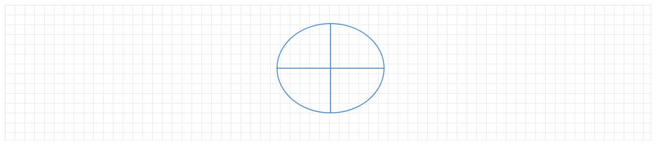

- Other options can be found in the Circle options
- Cross
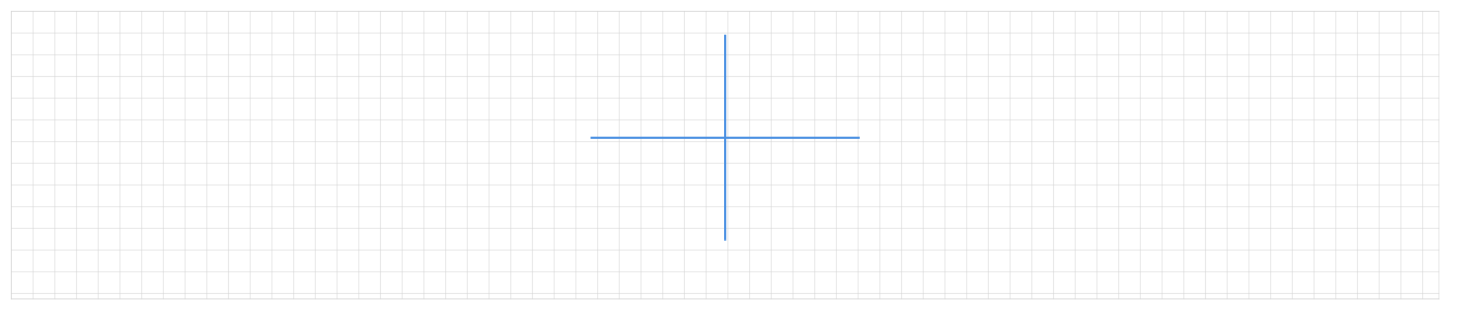

- Other options can be found in the Circle options
- Single Arrow-Head

- Options for Single Arrow-Head are shown below:

- Other options can be found in the Circle options
- Double Arrow-Head
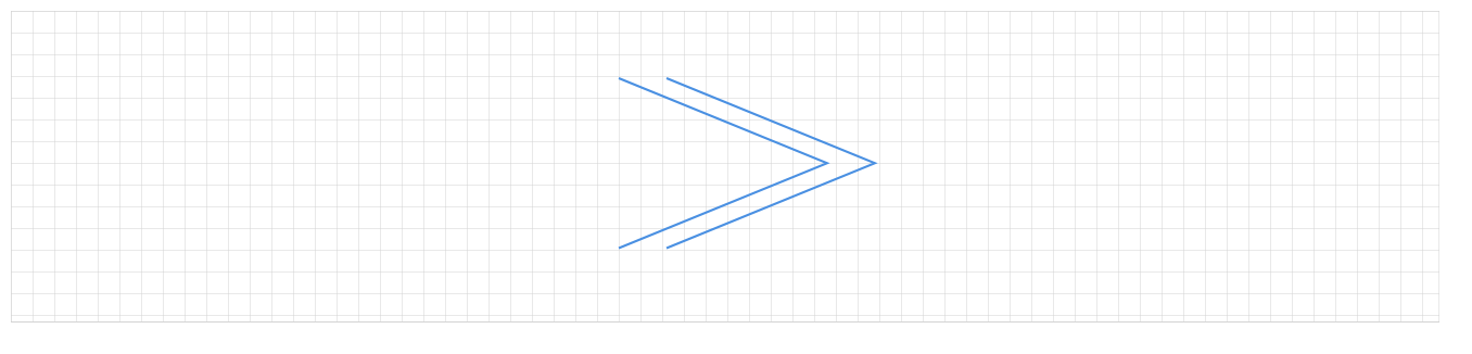
- Options for Double Arrow-Head are shown below:

- Click
 to increase/decrease separator distance
 - Other options can be found in the Circle options
- Arrow-Head Shape

- Options for Arrow-Head Shape are shown below:

- Drag
 to increase/decrease separator distance
 - Other options can be found in the Circle options
- Curve-Arrow-Head
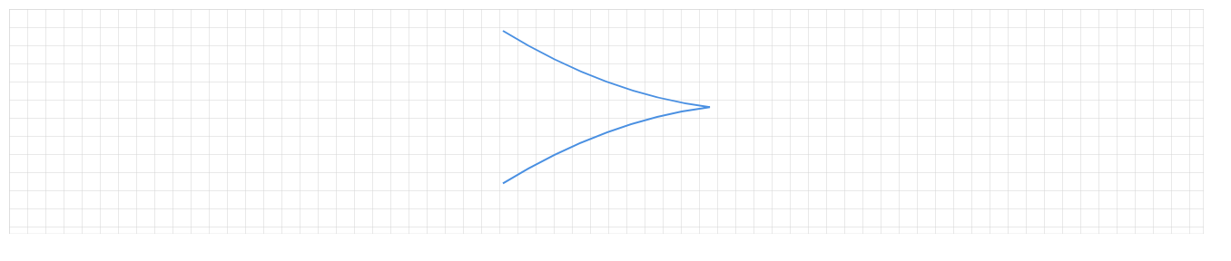
- Options for Curve-Arrow-Head are shown below:

- Other options can be found in the Circle options
Graph/Diagram Examples
Section titled “Graph/Diagram Examples”